Accelerometer specifications explained: what to look for and why it matters
Understand the critical performance parameters behind accelerometers—from bias voltage to cross-axis error—and how they impact data quality and test accuracy.
Introduction
Choosing the right accelerometer isn’t just about shape and size. Understanding the key specifications—like bias voltage, cross-axis error, and base strain—is essential to match the sensor to your test setup and avoid data distortion.
This guide outlines the most important accelerometer specifications and what they mean in real-world applications.
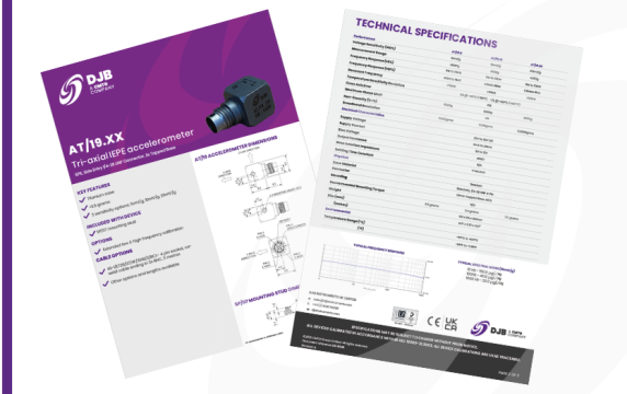
Constant current supply
2–20 mA, 15–35V DC
This is the operating power range for IEPE (Integrated Electronics Piezoelectric) accelerometers. It ensures compatibility with a wide range of off-the-shelf data acquisition systems. Always check that your system’s supply matches these limits for proper operation.
Settling time
This refers to the time it takes for an IEPE accelerometer’s internal electronics to stabilise at its bias voltage once powered. During this time, readings may be inaccurate, so it’s important to allow for this delay before starting measurements.
Cross-axis error
Cross-axis error represents the percentage of unwanted output measured in the primary axis due to vibration input from a perpendicular (cross) direction. It’s typically less than 5% in quality sensors, but it can worsen over time.
DJB’s Konic Shear® design naturally minimises cross-axis effects thanks to its radial geometry, providing long-term stability that outperforms conventional designs.
Bias voltage
Relevant only to IEPE accelerometers, bias voltage is the DC operating level of the internal amplifier circuit. It varies by manufacturer, but a higher value isn't necessarily better — it’s simply a result of the electronics design.
Saturation limit
This is the maximum vibration amplitude the accelerometer can measure before it clips or distorts. It defines the sensor’s peak measuring range and should always be matched to the expected signal levels in your test.
Base strain/base bending
Base strain occurs when the accelerometer's mounting surface bends during testing, causing strain to transfer into the piezoelectric element and generate false output. This is a known error source, especially in compression-mode accelerometers.
Shear and Konic Shear® designs, like those from DJB, significantly reduce this issue by mechanically isolating the sensing element from the mounting strain.
Want to explore our full range of accelerometers?
Browse DJB’s product portfolio to find the right sensor for your application or reach out for expert advice.
See the full range of accelerometers
Contact our experts or call us on +44 (0)1638 712 288

Dive into DJB’s growing library of expert-written resources, including technical articles, selection guides, and in-depth explainers on accelerometers, cables, and signal conditioning.
Whether you’re specifying new sensors or troubleshooting complex setups, our content is designed to support your success.