Helitune’s focus on engineering support services includes the adaptation of Tracking Systems for Rotor Towers to individual customer specifications, to help OEMs and operators make their Rotor Tower measurements more sophisticated and reliable. Helitune has recently been working with various OEMs to engineer and deliver the installation of a bespoke Rotor Tower Blade Tracking System.
Background
During production, qualification, maintenance, or repair of main rotor blades, Rotor Test Stands are regularly utilised within a static rotor head environment in order to simulate the forces to which these blades will be subjected, before installing onto a helicopter. Different measurements provide information on the status of the blades in terms of their interaction, e.g. thrust, drag (lead/lag), tip tracking, vibration characteristics, etc.
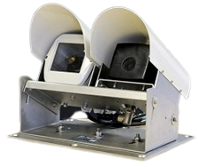
The WhirlTrak system comprises a permanently-installed tracking camera (Helitune’s own proven RT-TipTrak design), along with an associated track measurement system, supported by a wind measurement system and (optional) CCTV camera.
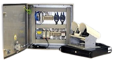
Helitune Engineers were able to integrate the system with the tower control system, in accordance with the OEM’s specific requirements, so that it benefits from computerised test reports to replace the previous paper-based reporting system, making analysis of the results much easier and more efficient.
Operation
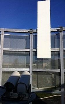
- A whiteboard ‘target’ is provided to ensure effective operation across a wide range of light conditions.
- Additional floodlight can be provided for operation during darkness, allowing continuous 24-hour tracking operation.
Analysis of results and user interface details
The user interface is programmed so that no other software is required for rotor track data acquisition, providing a fully integrated solution for the configuration of the RT-TipTrak tracking camera, display of real-time results, display of flat track, and collective track plots, calculation of blade adjustments, storage of track result data and generation of the output data report. All track measurement results are stored onto an MS SQL database for data archiving and subsequent retrieval.
The user interface allows for the review of previous rotor tower track results. Data collection activities are organised into sequences of ‘Tests’ and ‘Runs’. This allows multiple measurement runs to be completed on a blade set as part of the same test, facilitating simple retrieval and review of all measured data from a specific blade set. Tracking runs are pre-configured according to the required blade measurement procedure – multiple blade measurement procedures can be configured for each blade. System operators are able to easily select the required blade measurement procedure at the beginning of a test, allowing the system to automatically pre-configure itself into the required operating state.
Data reports are generated automatically and all data can be exported into an MS Excel compatible storage format – allowing complete flexibility in formatting and presentation of output results, certificates, and reports.
The Rotor Tower Controller software automatically configures the blade tracker hardware according to the pre-selected blade type. Live track results are displayed using both real-time current and averaged markers. Stored results for each data measurement point are plotted to the historic display graph in the centre of the live track display.
Historic results can be viewed using the Rotor Tower Software or exported automatically to MS Excel for report template generation.
Outline specification
- Provision of continuous real-time track measurement display
- Measured rotor track accuracy of better than ±1.27mm (±0.050 inch)*
- Measured rotor track resolution of better than ±1.27mm (±0.050 inch)*
- Averaged rotor track resolution of better than ±0.254mm (±0.010 inch)*
- Rotor RPM measurement range of 60RPM to 1200RPM
- Optional digital I/O interface to Rotor Tower Control System for tower state recognition (collective pitch interface)
- Digital serial O/P broadcast interface for transmission of track results to third party systems
- Automatic configuration of RT-TipTrak tracking device based upon blade type to be tested
- Track results storage based upon user track condition selection Blade adjustment calculation based upon measured track results
- Track data archiving and results report generation
- Operating temperature range of -20°C to +60°C for all Rotor Tower mounted hardware
- Solid-state solution with no moving parts
- Wide field of view measurement tracker, allowing a fixed installation to track multiple blade types
- The tracking camera is a variant of the existing Helitune RT-TipTrak product, which has proven performance in a permanently installed DO-160E aircraft environment *
Note: Stated accuracy achievable depends upon physical installation characteristics of the individual rotor tower.